
Instructions and Documentation
Junction Box Layout Instructions
Because of the unique configuration of the SRD-N1LL housing, the fixed junction boxes and electrical terminal boxes must be positioned in a certain way relative to one another in order to accept the SRD-N1LL. If the junction boxes can be repositioned, such as by temporarily loosening up the mounting screws, then there is a lot more flexibility.
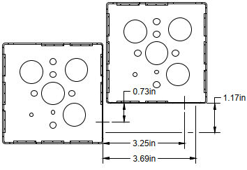
Because junction box knock-out locations aren’t standardized, and the knock-out holes themselves may be imperfect, the best approach is to create an installation template based on the following minimum dimensions to align the desired knock-out holes at their edges.
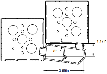
In cases where you need to specify junction box locations based on the centerlines of the knock-out holes, use the dimensions below as a minimum. However, with the variability of knock-out holes, you may want to pad those minimums by 0.02-0.03”.
SRD-N1LL Installation Instructions

HAZARD OF ELECTRIC SHOCK, ARC FLASH, OR EXPLOSION
Read, understand, and follow the instructions before installing this product.
This product must be installed and serviced only by qualified electrical personnel.
This product must be installed using safe electrical work practices and in accordance with all applicable codes for your location. (e.g., NFPA 70E for the USA)
Turn off all power supplying this product before working on or inside the product.
Use a properly rated voltage sensing device to confirm that power is off.
DO NOT DEPEND ON THIS PRODUCT FOR VOLTAGE INDICATION
Failure to follow these instructions will result in death or serious injury.
Disconnect and lock out all power sources before beginning the installation.
Connect the relay to desired enclosures by feeding the wires and the threaded nipples of the housing through knock out holes in the enclosures.
Secure the housing to the enclosures using the provided conduit nuts.
Connect the Coil Leads:
• Depending on the application requirements, connect either the low voltage lead (10-30 VAC/DC, coded white with blue stripe) or the high voltage lead (120 VAC, coded white with black stripe) to the (+) source termination point.*
• Insulate connections in accordance with local electrical codes.
Connect the Relay Contact Leads:
• Connect the relay common lead (coded yellow) to the switched load.
• Depending on the application requirements, connect the relay N.O. lead (coded orange) and/or* N.C. lead (coded blue) to switched load.
• Insulate connections in accordance with local electrical codes.
Secure the enclosures and reconnect power.
• Connect the coil common lead (coded white with yellow stripe) to the (-) source termination point.
* NOTE: All non-terminated wire ends must be isolated or insulated in accordance with the local electrical code requirements.
Downloads
Specifications
UL Type 1 enclosure made of UL94 5VA compliant plastic containing One (1) Single-Pole Double-Throw Relay with nominal rating of 10 Amps @ 277 VAC. Relay status is indicated by LED, with LED-on indicating voltage across the coil.
The housing dimensions are 3.76” x 1.48” x 1.25”, including two 0.5“ NPT nipples.
UL Listed, UL916, UL864, accepted for use in plenum per UL 2043, for general signaling (G), enclosed energy management equipment (EM), smoke control, and fire alarm equipment (F)
Relay Contact Ratings
General Purpose
Pilot Duty
Motor Loads
Electrical Duty
10 Amp @ 277 VAC
B-300, R-300
1/3 HP @ 120 VAC (N/O)
1/2 HP @ 277 VAC (N/O)
100 Thousand Cycles at 10A @ 277 VAC (N/O)
30 Thousand Cycles at 10A @ 277 VAC (N/C)
Operation Time
Ambient Temp.
Humidity Range
20 ms
-30°F to 140°F (-34°C to 60°C)
Non-condensing 5% to 95%
Coil Input Options

120 VAC Coil Input Typical Performance
Current @ 120 VAC is 42 mA
Pull-In @ 88 VAC @ 31 mA
Drop-Out @ 27 VAC @ 9 mA
10-30 VAC/VDC Coil Input Typical Performance
45 mA @ 30 VDC
Pull-In @ 9.5 VDC @ 25 mA
Drop-Out @ 4.1 VDC @ 6 mA
94 mA @ 30 VAC
Pull-In 8.2 VAC @ 3 mA
Drop-Out 3.3 VAC @ 3 mA
Certifications
Underwriters Laboratory performed all relevant certification testing under UL File # S36117. The SRD-N1LL was certified to the following standards:
UL864, Control Units and Accessories for Fire Alarm Systems
UL916, Energy Management Equipment
UL2017, General-Purpose Signaling Devices and Systems
ULC-S527-11AM, Control Units and Accessories for Fire Alarm Systems
ULC/ORD-C100-13 Smoke Control System Equipment
C22.2 No. 205-17, Signal Equipment